Application notes

Technical notes

Ask an engineer


Publications
United States (EN)
Select your region or country.
Cameras for 3D imaging
John Gilmore, Hamamatsu Corporation
Slawomir Piatek, PhD, Hamamatsu Corporation & New Jersey Institute of Technology
November 2, 2014
Gauging the distance, size, and shape of an object is of paramount and self-evident practical importance in everyday life. Nature has evolved a variety of ways for organisms to obtain 3D information: stereoscopic visions utilizing two or more eyes, and sonar ranging are two examples. Extending this ability to inanimate systems such as robots, “decision makers” in automated assembly lines, or self-driving vehicles has been and continues to be an active area of research and development.
Among the several techniques that use light for measuring depth, two bear relevance to the current article. In the first, the distance or range R to a point on the target surface derives from the time ΔT it takes a pulse of light (for example, emitted by a laser) to travel from the observer to the point and back, namely , where c is the speed of light in vacuum and n is the index of refraction of the surrounding medium. In the second technique, R derives from the phase difference ΔΦ between the emitted intensity-modulated beam of light and its reflection; here, , where f is the frequency of modulation. Prior to the mid-1990s, a 3D camera employing either of these two techniques required a mechanical scanning system to sample an array of points on the target surface. One limitation of such an arrangement is a compromise between the frame rate and density of sampled points, where the former affects the temporal accuracy of depth measurement for a moving target, whereas the latter affects the spatial resolution of the features on the target. This compromise could have been lessened if it were possible to measure simultaneously all of the distances to an array of points on the target surface. This is now possible.
The breakthrough is the development of a CMOS-architecture imaging array where each pixel is a Photonic Mixer Device (PMD). The left panel in Figure 1 depicts a simplified structure of a PMD. An internal electric field directs the photogenerated charge carrier (electron) to one of the two charge storage locations. Two external signals Vtx1 and Vtx2 control the strength and direction of the electric field and, therefore, they also control how much charge each storage location receives in response to incident light. The output signals V1 and V2 are a measure of how much charge has been accumulated in locations 1 and 2, respectively. The right panel of Figure 1 shows a simplified electrical equivalent circuit of a PMD. The main components are a photodiode (generator of photo-charge), two capacitors (charge storage locations), and switches (responsible for directing the photo-charge to the appropriate capacitors). A discussion of a more complete equivalent circuit and how it operates is below.
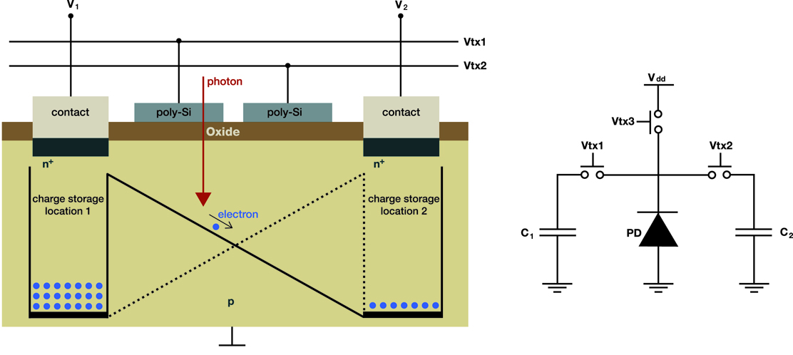
Figure 1. A simplified structure of a PMD (left panel) and its equivalent electrical circuit (right panel).
In one common arrangement, a 3D camera system illuminates the scene with an intensity-modulated infrared light. The optics of the system creates an image of the scene on the array of PMD pixels. For each pixel, the system determines an autocorrelation function between the electrical signal that modulates the emitted light and the electrical signals coming from the two capacitors. Sampling the resulting function four times per period gives the phase shift, strength of the returned signal, and the background level using well-known mathematical relations. The distance is proportional to the phase shift.
In the second arrangement, a 3D camera system illuminates the scene with a pulse of infrared light of duration T0 (from nanoseconds to microseconds) while simultaneously making the pixels sensitive to light for the duration of 2T0. During the first half of 2T0, only one of the two capacitors collects the charge, whereas during the second half, only the second capacitor does. The distance imaged by a pixel derives from the relative amounts of charge collected by each of the two capacitors. A single pulse of light generally produces too little signal in the capacitors; thus, the system illuminates the scene with thousands of pulses appropriately spaced in time so that the capacitors accumulate enough charge to yield accurate distance. In literature, this type of a 3D camera is referred to as an indirect time-of-flight (I-TOF) camera, and the remainder of this article describes its operation in greater detail.
Principles of operation
Figure 2 explains the principles of operation of a “single-pixel” I-TOF camera, assuming one pulse of light per frame and the absence of background light and dark current. The shaded region depicts an equivalent electrical circuit of the pixel.
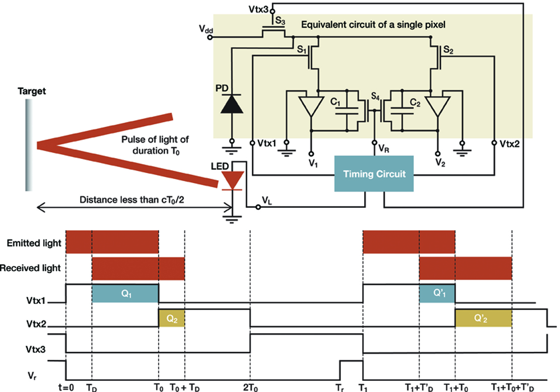
Figure 2. Principles of operation of a single pixel in an I-TOF camera.
The pixel consists of a photodiode (PD) whose output connects to three MOSFET switches S1, S2, and S3. The first two connect to the charge integrators C1 and C2, respectively, whereas the third connects to an external voltage source Vdd. The timing circuit generates CMOS-compatible logic signals Vtx1, Vtx2, and Vtx3, which drive the switches. A signal that is “high” turns a switch ON, whereas a signal that is “low” turns a switch OFF. A dual switch S4 shunts C1 and C2; the signal VR, also produced by the timing circuit, controls its operation. The pixel outputs two voltages V1 and V2 per frame from which the distance to an element of the target imaged onto the pixel can be calculated. For an array of (m, n) pixels, the camera determines m x n independent distances to the target elements, one for each pixel, per frame.
To measure the distance to a point on the target, the timing circuit produces a signal VL that causes the LED or laser diode to emit a pulse of light of duration T0. Refer to the timing diagram at the bottom of Figure 2. At the instant of emission (t = 0) Vtx1 goes high turning S1 ON. The other three signals are low keeping S2, S3, and S4 OFF. At t = TD the leading edge of the reflected pulse arrives, and the photodiode begins to generate current, building charge Q1 and, thus, voltage V1 on the capacitor C1. At t = T0, Vtx1 goes low turning S1 OFF, while at the same time Vtx2 goes high turning S2 ON. The signals Vtx3 and VR remain low keeping S3 and S4 OFF. The photodiode continues to generate current, which now builds charge Q2 and, thus, voltage V2 on the capacitor C2. At t = T0 + TD the trailing edge of the pulse arrives: the photodiode stops generating current and, therefore, Q2 and V2 have reached their final values even though S2 remains ON. At t = 2T0, Vtx2 goes low turning S2 OFF, while at the same time Vtx3 goes high turning S3 ON. The switch S3 now holds the photodiode to Vdd, ensuring that (if present) both dark current and current due to background light are prevented from flowing to C1 and C2. The camera system now samples V1 and V2 and calculates the distance using:
Equation 1
The capacitors C1 and C2 hold their charge until t = TR when the signal VR goes high causing S4 to shunt and reset the capacitors. At t = T1 the camera is ready for the next frame.
Suppose that between t = 2T0 and t = T1 the target has moved to a greater distance. The timing diagram shows that for this frame, the charge collected on C1 is less than Q1 and the charge on C2 is greater than Q2. The resulting smaller V1 and larger V2 imply a greater distance for this frame, as expected from Equation 1. Since the smallest value of V1 is 0, the maximum distance that can be measured, RMAX, is cT0/2.
The duration of the pulse limits RMAX. For a pulse with T0 = 30 ns and air as the medium, RMAX = 4.5 m. If the duration of a pulse is fixed at T0, RMAX can be extended by introducing a time delay τ between the instant the light pulse is emitted (t = 0) and the instant Vtx1 turns high (now at t = τ). Vtx2 turns high at t = T0 + τ when Vtx1 turns low. Doing this extends the range in Equation 1 by cτ/2.
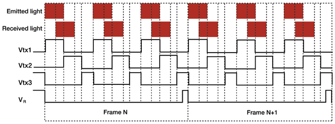
Figure 3. Timing diagram for two consecutive frames, each produced from three pulses of light. The target is stationary.
The amount of light in a returning reflected pulse depends on the amount of light in the emitted pulse, the type of medium in which the pulse propagates, distance to the target, and the color, orientation, and smoothness of the reflecting surface. The amount is generally too small to yield an accurate measurement; therefore, thousands of pulses of light may be used for a single frame. Figure 3 is a simplified timing diagram depicting signals Vtx1, Vtx2, Vtx3, and VR for two consecutive frames, each produced from three pulses of light.
Many of the potential applications of an I-TOF camera require that it is able to operate in full sunlight or indoor artificial lighting. Background light carries no information about the target, and if it contributes charge to C1 and C2, the resulting distance measurement will be erroneous. Using a narrow bandpass filter centered on the wavelength of the emitted pulses suppresses the background but does not completely eliminate it. Dark current, continuously generated by the photodiode, has a similar effect on the distance measurement as a non-varying background. Cooling the camera reduces dark current, but this approach may be impracticable. To alleviate the effects of background and dark current, the camera obtains sequentially pairs of frames: the first “light” frame results from pulsed light, background, and dark current, whereas the second “dark” frame results from background and dark current. Subtracting the “dark” frame from the “light” frame produces a “corrected” frame.
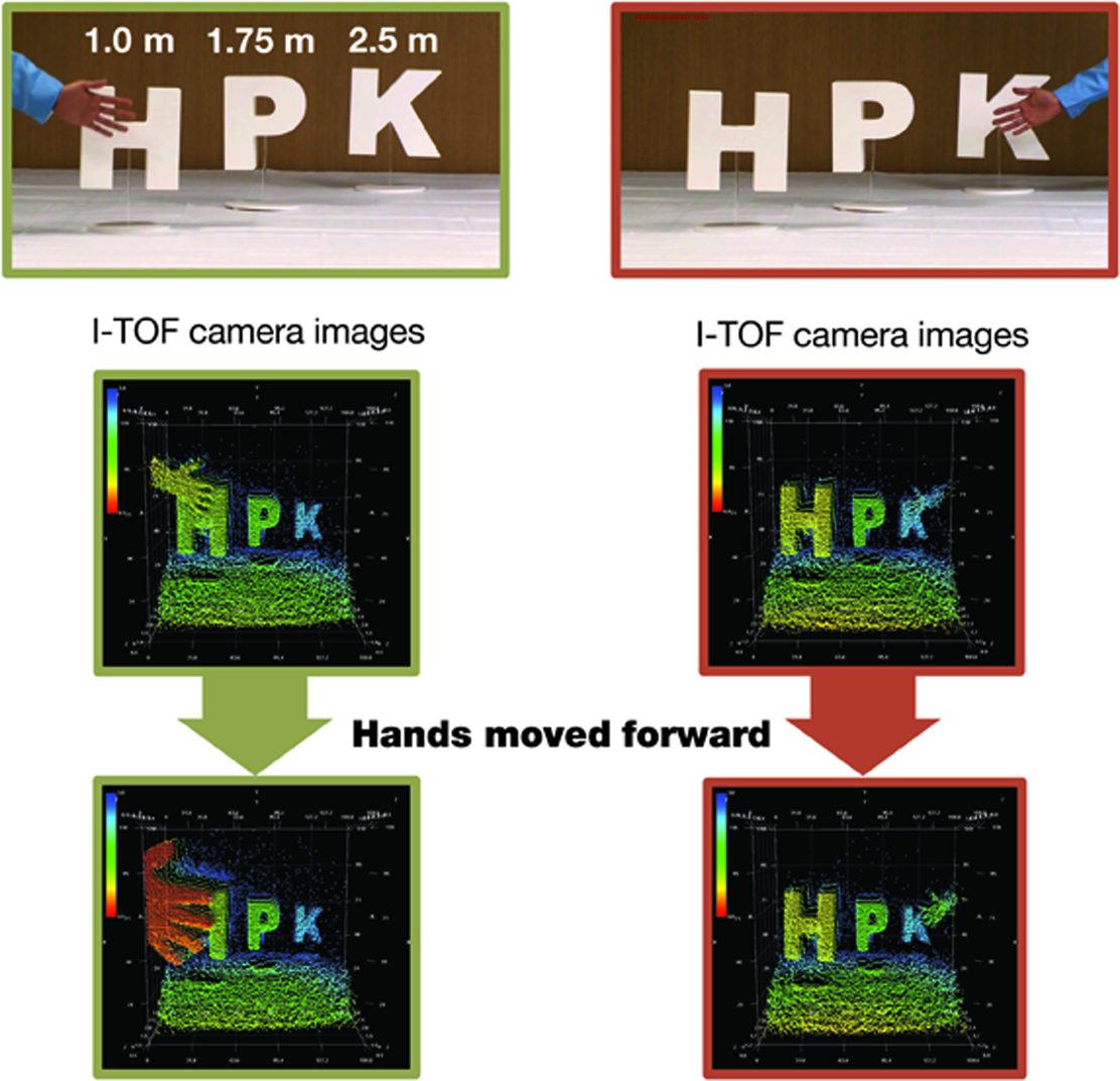
Figure 4. Example of an I-TOF camera output image with 3D information.
The top two panels in Figure 4 display scenes to be imaged with an I-TOF camera. In both scenes, the letters H, P, and K are 1.0 m, 1.75 m, and 2.5 m, respectively, from the camera, but the hand is not. In the left scene, the hand is in front and close to the letter H, whereas in the right scene, it is in front and close to the letter K. The panels in the middle row are the corresponding distance images acquired by a camera system using 10-μs pulses (3000 pulses per frame) from an 8X8 array of LEDs (λ=870 nm, FWHM = 45 nm), IR-transmission filter HOYA IR83N, f/1.2 lens (focal length 8 mm), and a 160 x 120 pixel2 PMD imaging array (Hamamatsu S11963-01CR, pixel size 30 μm x 30 μm, FOV = 37.5° x 27.7°). The imaged distance is color-coded with blue corresponding to the farthest and red to the closest. The panels in the bottom row show that the color (distance) of the hands becomes redder (smaller) as they are moved closer to the camera. How small a movement can a camera detect?
Equation 2 shows that the uncertainty σR in the measured distance by a pixel increases linearly with T0 and decreases as inverse square root with increasing signal-to-noise (S/N) ratio.
Equation 2
The noise N in the equation is a square-root of the sum in quadrature of the signal (photon) shot noise Nss, dark current shot noise Nds, background shot noise Nbs, and read noise Nr. Equation 2 assumes that the target is at RMAX/2 so that the amount of charge accumulated by each capacitor is the same. If the photon shot noise is dominant, σR reduces to cT0/4√ Ne, where Ne is the number of photoelectrons accumulated together by C1 and C2. Figure 5 is a plot of measured σR as a function of Ne. Here, the target is at R = RMAX/2, T0 = 30 ns, and there are 15,000 pulses per frame and no ambient light. The amplitude of the pulses is varied to achieve different values of Ne.
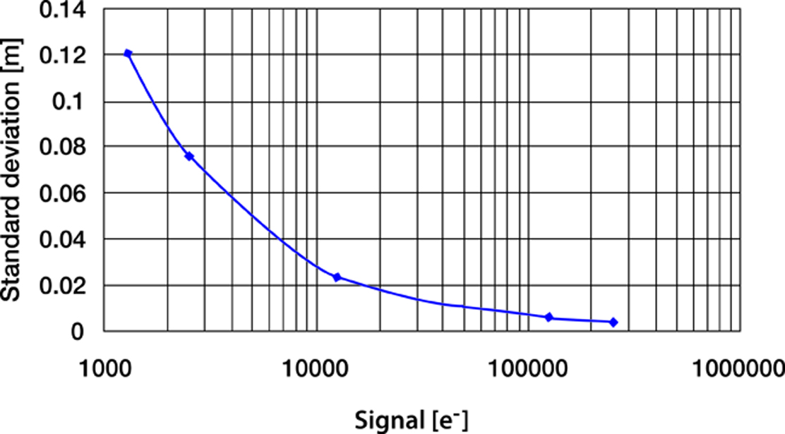
Figure 5. Distance uncertainty as a function of collected charge.
The plot shows that σR decreases with Ne as expected from Equation 2 and that the fractional error σR/R (R = 2.25 m) decreases from about 5.3% to about 0.44% as the collected signal increases from about 125 e- to about 275,000 e-. The more light there is, the better accuracy of the measured distance.
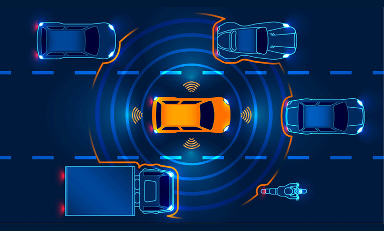
An achievable uncertainty of a few centimeters for a distance of a few meters is low enough for I-TOF cameras to find numerous practical applications. For example, the automotive industry has developed I-TOF camera systems that warn a driver (or take an independent action) about a possible frontal collision with an object such as another car or a pedestrian. Another use of I-TOF cameras is in robots that perform vision-based tasks in hazardous environments such as mines, mills, or manufacturing plants. Even in the entertainment industry, I-TOF cameras are used: video game developers have enhanced human-machine interaction in games requiring accurate distance information such as virtual baseball, boxing, or combat. By developing artificial and real time 3D vision, humans have finally caught up with what nature has been able to do for millions of years.
Note
A version of this article was published in the November 2014 issue of Photonics Spectra.
- Confirmation
-
It looks like you're in the . If this is not your location, please select the correct region or country below.
You're headed to Hamamatsu Photonics website for US (English). If you want to view an other country's site, the optimized information will be provided by selecting options below.
In order to use this website comfortably, we use cookies. For cookie details please see our cookie policy.
- Cookie Policy
-
This website or its third-party tools use cookies, which are necessary to its functioning and required to achieve the purposes illustrated in this cookie policy. By closing the cookie warning banner, scrolling the page, clicking a link or continuing to browse otherwise, you agree to the use of cookies.
Hamamatsu uses cookies in order to enhance your experience on our website and ensure that our website functions.
You can visit this page at any time to learn more about cookies, get the most up to date information on how we use cookies and manage your cookie settings. We will not use cookies for any purpose other than the ones stated, but please note that we reserve the right to update our cookies.
1. What are cookies?
For modern websites to work according to visitor’s expectations, they need to collect certain basic information about visitors. To do this, a site will create small text files which are placed on visitor’s devices (computer or mobile) - these files are known as cookies when you access a website. Cookies are used in order to make websites function and work efficiently. Cookies are uniquely assigned to each visitor and can only be read by a web server in the domain that issued the cookie to the visitor. Cookies cannot be used to run programs or deliver viruses to a visitor’s device.
Cookies do various jobs which make the visitor’s experience of the internet much smoother and more interactive. For instance, cookies are used to remember the visitor’s preferences on sites they visit often, to remember language preference and to help navigate between pages more efficiently. Much, though not all, of the data collected is anonymous, though some of it is designed to detect browsing patterns and approximate geographical location to improve the visitor experience.
Certain type of cookies may require the data subject’s consent before storing them on the computer.
2. What are the different types of cookies?
This website uses two types of cookies:
- First party cookies. For our website, the first party cookies are controlled and maintained by Hamamatsu. No other parties have access to these cookies.
- Third party cookies. These cookies are implemented by organizations outside Hamamatsu. We do not have access to the data in these cookies, but we use these cookies to improve the overall website experience.
3. How do we use cookies?
This website uses cookies for following purposes:
- Certain cookies are necessary for our website to function. These are strictly necessary cookies and are required to enable website access, support navigation or provide relevant content. These cookies direct you to the correct region or country, and support security and ecommerce. Strictly necessary cookies also enforce your privacy preferences. Without these strictly necessary cookies, much of our website will not function.
- Analytics cookies are used to track website usage. This data enables us to improve our website usability, performance and website administration. In our analytics cookies, we do not store any personal identifying information.
- Functionality cookies. These are used to recognize you when you return to our website. This enables us to personalize our content for you, greet you by name and remember your preferences (for example, your choice of language or region).
- These cookies record your visit to our website, the pages you have visited and the links you have followed. We will use this information to make our website and the advertising displayed on it more relevant to your interests. We may also share this information with third parties for this purpose.
Cookies help us help you. Through the use of cookies, we learn what is important to our visitors and we develop and enhance website content and functionality to support your experience. Much of our website can be accessed if cookies are disabled, however certain website functions may not work. And, we believe your current and future visits will be enhanced if cookies are enabled.
4. Which cookies do we use?
There are two ways to manage cookie preferences.
- You can set your cookie preferences on your device or in your browser.
- You can set your cookie preferences at the website level.
If you don’t want to receive cookies, you can modify your browser so that it notifies you when cookies are sent to it or you can refuse cookies altogether. You can also delete cookies that have already been set.
If you wish to restrict or block web browser cookies which are set on your device then you can do this through your browser settings; the Help function within your browser should tell you how. Alternatively, you may wish to visit www.aboutcookies.org, which contains comprehensive information on how to do this on a wide variety of desktop browsers.
5. What are Internet tags and how do we use them with cookies?
Occasionally, we may use internet tags (also known as action tags, single-pixel GIFs, clear GIFs, invisible GIFs and 1-by-1 GIFs) at this site and may deploy these tags/cookies through a third-party advertising partner or a web analytical service partner which may be located and store the respective information (including your IP-address) in a foreign country. These tags/cookies are placed on both online advertisements that bring users to this site and on different pages of this site. We use this technology to measure the visitors' responses to our sites and the effectiveness of our advertising campaigns (including how many times a page is opened and which information is consulted) as well as to evaluate your use of this website. The third-party partner or the web analytical service partner may be able to collect data about visitors to our and other sites because of these internet tags/cookies, may compose reports regarding the website’s activity for us and may provide further services which are related to the use of the website and the internet. They may provide such information to other parties if there is a legal requirement that they do so, or if they hire the other parties to process information on their behalf.
If you would like more information about web tags and cookies associated with on-line advertising or to opt-out of third-party collection of this information, please visit the Network Advertising Initiative website http://www.networkadvertising.org.
6. Analytics and Advertisement Cookies
We use third-party cookies (such as Google Analytics) to track visitors on our website, to get reports about how visitors use the website and to inform, optimize and serve ads based on someone's past visits to our website.
You may opt-out of Google Analytics cookies by the websites provided by Google:
https://tools.google.com/dlpage/gaoptout?hl=en
As provided in this Privacy Policy (Article 5), you can learn more about opt-out cookies by the website provided by Network Advertising Initiative:
http://www.networkadvertising.org
We inform you that in such case you will not be able to wholly use all functions of our website.
Close