Application notes
Technical notes
Ask an engineer
Publications
United States (EN)
Select your region or country.
MEMS-FPI Questions & Answers
What is a MEMS-FPI spectrum sensor?
The MEMS-FPI (short for microelectromechanical system-based Fabry-Perot interferometer) spectrum sensor is built upon the optical design first introduced in 1899 by French physicists, Charles Fabry and Alfred Perot. This optical design centers around the use of two parallel mirrors or reflective surfaces surrounding a cavity. As the volume of this cavity changes, so too does the wavelength of light that passes through it.
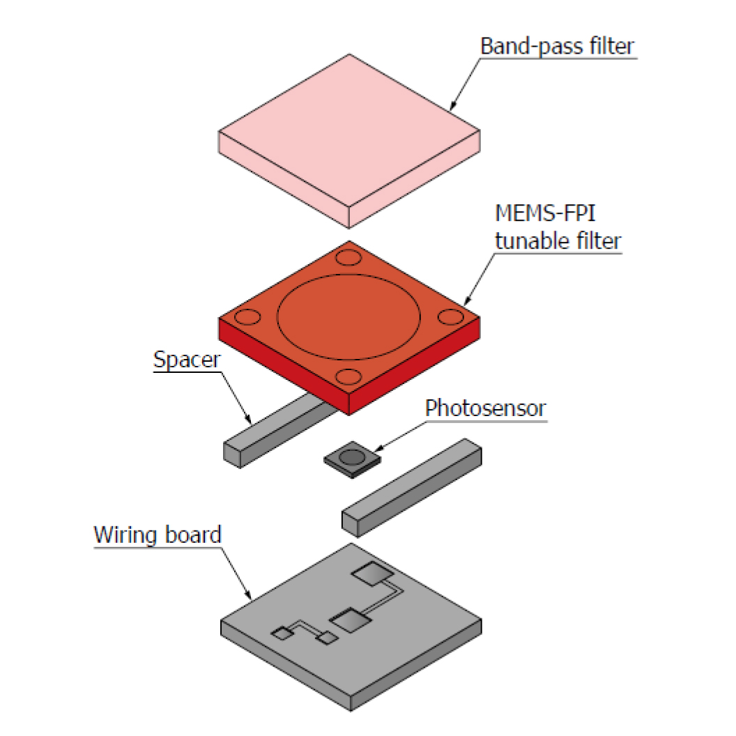
Figure 1. Internal structure of the MEMS-FPI
In the case of the MEMS-FPI spectrum sensor from Hamamatsu Photonics, the FPI is incorporated into the tunable filter design. Micromachined into this tunable filter are laminations of dielectric coatings (such as SiO2, SiN, or poly-Si), which make up the upper and lower mirrors. In between these mirrors is an air gap. As seen in Figure 1, light passes through a band-pass filter and then travels through the tunable filter. When voltage is applied to the MEMS-FPI spectrum sensor, an electrostatic force is produced between the two mirrors in the filter. The higher the applied voltage, the higher the electrostatic force and, therefore, the closer the mirrors are to one another; the shallower the air gap between them, the shorter the wavelength of light transmitted (and vice versa). The MEMS-FPI spectrum sensor contains an InGaAs PIN photodiode to collect the transmitted near-infrared (NIR) light. Depending on the version of the spectrum sensor used and its corresponding band-pass filter, light in the following bands can be detected (Table 1):
| Wavelengths detected | Part number | Device description |
|---|---|---|
| 1350 to 1650 nm | C14272 | MEMS-FPI spectrum sensor |
| C15712 | MEMS-FPI spectroscopic module | |
| 1550 to 1850 nm | C13272-02/-03 | MEMS-FPI spectrum sensor |
| C15713 | MEMS-FPI spectroscopic module | |
| 1750 to 2150 nm | C14273 | MEMS-FPI spectrum sensor |
| C15714 | MEMS-FPI spectroscopic module |
When applying voltage to a MEMS-FPI spectrum sensor, it is of utmost importance to keep in mind the possibility of pull-in phenomenon. Pull-in occurs when the electrostatic forces used to draw the mirrors closer together exceeds the spring force used to pull the upper mirror away from the lower mirror. If this happens, the mirrors effectively stick to one another—a process that is very difficult, if not impossible, to reverse. When this happens, the wavelengths measured become unreliable as the spectrum sensor is no longer accurately correlating a certain mirror distance to the wavelength transmitted. As seen in Figure 2, factors such as applied voltage and operating temperature contribute to the likelihood of pull-in occurring.
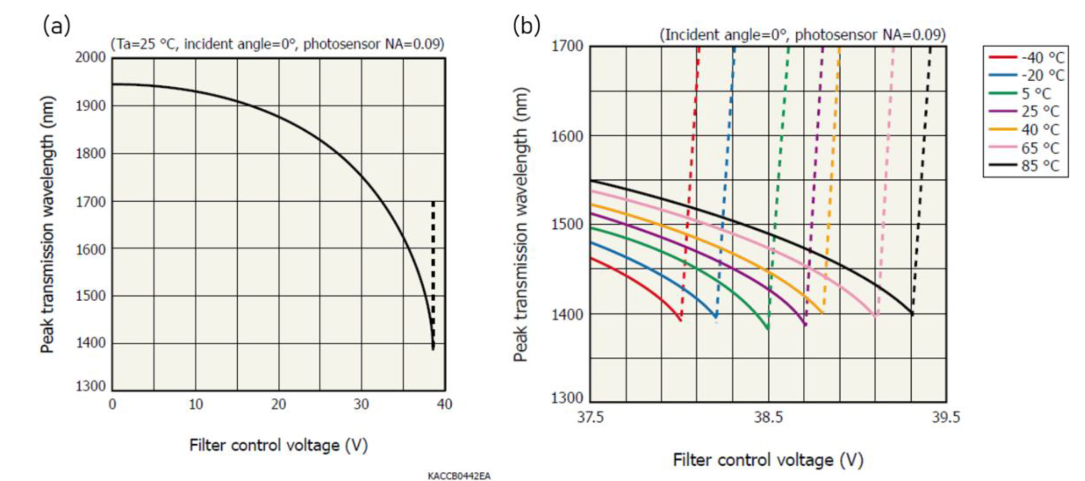
Figure 2. (a) Pull-in phenomenon’s relationship to applied voltage (note: pull-in occurs at the dotted line). (b) Pull-in phenomenon’s relationship to operating temperature
To ensure the correct voltage is applied to the spectrum sensor, the appropriate calibration coefficients need to be applied. These coefficients are device-specific, so each spectrum sensor head and each evaluation board (as pictured in Figure 3) must have its calibration coefficients applied to ensure proper use and accurate results.
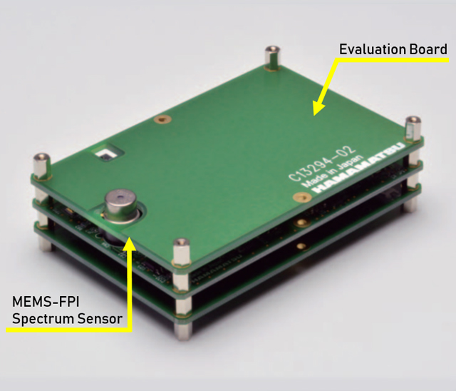
Figure 3. MEMS-FPI spectrum sensor and evaluation board (sold separately)
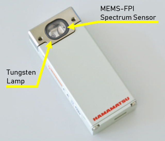
Figure 4. MEMS-FPI module (containing MEMS-FPI spectrum sensor, evaluation circuitry, and lamp)
To simplify handling of the MEMS-FPI spectrum sensor, Hamamatsu Photonics has introduced the MEMS-FPI module. Built-in capabilities such as preprogrammed calibration coefficients remove the need for users to manually upload individual coefficients—instead, these values are loaded into the EEPROM of the board housed in the module and automatically read once the device is identified in the evaluation software. To streamline optical design, this device contains a built-in lamp: users can either operate the MEMS-FPI with the lamp on for reflection measurements or with the lamp off for transmission measurements using an external source. As seen in Figure 4, in its standard form, the module can be used for free-space measurement. However, a separate SMA fiber adapter is available for those looking for fiber-coupled measurements as well.
An additional feature of the module that is not included in the sensor with evaluation board option is the incorporation of temperature compensation functions. As discussed with regards to the pull-in phenomenon, temperature plays a significant role in the position of the mirrors in the tunable filter and the corresponding measured wavelength. To correct for any inaccuracies due to changes in temperature, temperature correction algorithms have been designed and integrated into the software, thus providing added reliability and temperature stability in MEMS-FPI performance.
For what applications can you use the MEMS-FPI?
With sensitivity in various bands of the NIR range, the MEMS-FPI can be used to observe key absorption lines for water, organic compounds, and inorganic compounds (Figure 5). This means that applications such as those listed below are possible:
- Moisture detection in skin or in paper materials
- Detection and analysis of organic compounds in agricultural and food products
- Detection of synthetic contaminants in agricultural and food products
- Plastic sorting
- Identification of various synthetics and fabrics
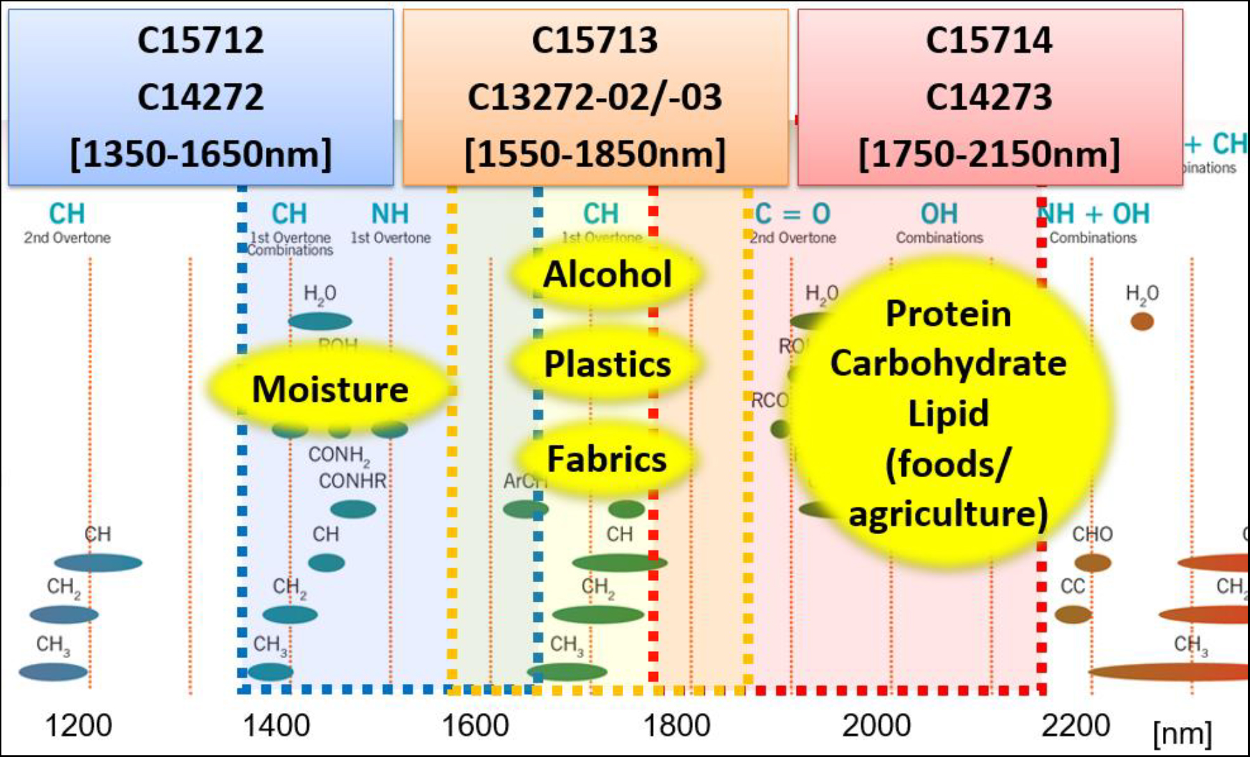
Figure 5. MEMS-FPI spectral coverages and related target compounds
Using their expertise in the manufacture of MOEMS (microoptoelectromechanical system) devices, Hamamatsu Photonics has achieved a compact design of the FPI. With its small form factor, the MEMS-FPI spectrum sensor can be integrated into portable solutions for its given application. For even quicker start-up, users can turn to the MEMS-FPI module; with the MEMS-FPI spectrum sensor, evaluation circuitry, built-in lamp for reflection measurements, and USB micro-B connector, all contained within a hand-held housing, this device shortens the time between the physical setup of optics and electronics, and measurement.
How does the MEMS-FPI compare with other NIR spectral sensors?
Compared to other interferometer spectral sensors (such as the MEMS-based FTIR engine), the MEMS-FPI excels in its compact design. When comparing between an interferometer-based spectrum sensor, such as the MEMS-FPI, and array-based spectrometers, we suggest users consider the specifications in Table 2 below when assessing which option may work for them.
Visit our main website for more product info
| MEMS-FPI Spectrum Sensor | MEMS-FPI Module | FTIR Engine C15511-01 | Uncooled InGaAs Spectrometer C14486GA | Cooled InGaAs Spectrometer C11118GA | |
|---|---|---|---|---|---|
| Spectral range | 1350-1650 nm, 1550-1880 nm, 1750-2150 nm | 1100-2500 nm | 950-1700 nm | 900-2550 nm | |
| Resolution (typical value) | 18-22 nm |
5.7 nm | 5 nm | 15 nm | |
| Technology | MEMS Fabry-Perot interferometer + InGaAs PIN photodiode |
MEMS Michelson interferometer + InGaAs PIN photodiode | Grating + uncooled InGaAs image sensor | Grating + cooled InGaAs image sensor | |
| Overall dimensions | 90 x 60 x 28.8 mm (mounted on board) | 74 x 32 x 16 mm | 76 x 57 x 49 mm | 80 x 60 x 12 mm | 218 x 142 x 82 mm |
| Range of integration times | Cannot be adjusted |
1-1000 μs | 6-40000 μs | ||
| Gain settings | 2 levels | 3 levels | 5 levels | N/A |
|
| Power requirements | USB bus powered |
USB bus + 12 V for cooling fan, +5V for cooling element | |||
SNR |
Good |
Very good |
|||
| Price range | $ |
$$ |
$$$ | ||
Table 2. General comparison of MEMS-FPI and other NIR spectral sensors
If you have a technical question you’d like to see answered on this page, email us.
Meet the engineer

As an Applications Engineer at Hamamatsu Corporation, Stephanie Butron is passionate about exploring the diverse projects and applications of Hamamatsu's customers, gaining insights into how the company can be of service. When she's not assisting researchers and professionals with their projects, Stephanie enjoys channeling her creativity into karaoke and cake decorating.
- Confirmation
-
It looks like you're in the . If this is not your location, please select the correct region or country below.
You're headed to Hamamatsu Photonics website for US (English). If you want to view an other country's site, the optimized information will be provided by selecting options below.
In order to use this website comfortably, we use cookies. For cookie details please see our cookie policy.
- Cookie Policy
-
This website or its third-party tools use cookies, which are necessary to its functioning and required to achieve the purposes illustrated in this cookie policy. By closing the cookie warning banner, scrolling the page, clicking a link or continuing to browse otherwise, you agree to the use of cookies.
Hamamatsu uses cookies in order to enhance your experience on our website and ensure that our website functions.
You can visit this page at any time to learn more about cookies, get the most up to date information on how we use cookies and manage your cookie settings. We will not use cookies for any purpose other than the ones stated, but please note that we reserve the right to update our cookies.
1. What are cookies?
For modern websites to work according to visitor’s expectations, they need to collect certain basic information about visitors. To do this, a site will create small text files which are placed on visitor’s devices (computer or mobile) - these files are known as cookies when you access a website. Cookies are used in order to make websites function and work efficiently. Cookies are uniquely assigned to each visitor and can only be read by a web server in the domain that issued the cookie to the visitor. Cookies cannot be used to run programs or deliver viruses to a visitor’s device.
Cookies do various jobs which make the visitor’s experience of the internet much smoother and more interactive. For instance, cookies are used to remember the visitor’s preferences on sites they visit often, to remember language preference and to help navigate between pages more efficiently. Much, though not all, of the data collected is anonymous, though some of it is designed to detect browsing patterns and approximate geographical location to improve the visitor experience.
Certain type of cookies may require the data subject’s consent before storing them on the computer.
2. What are the different types of cookies?
This website uses two types of cookies:
- First party cookies. For our website, the first party cookies are controlled and maintained by Hamamatsu. No other parties have access to these cookies.
- Third party cookies. These cookies are implemented by organizations outside Hamamatsu. We do not have access to the data in these cookies, but we use these cookies to improve the overall website experience.
3. How do we use cookies?
This website uses cookies for following purposes:
- Certain cookies are necessary for our website to function. These are strictly necessary cookies and are required to enable website access, support navigation or provide relevant content. These cookies direct you to the correct region or country, and support security and ecommerce. Strictly necessary cookies also enforce your privacy preferences. Without these strictly necessary cookies, much of our website will not function.
- Analytics cookies are used to track website usage. This data enables us to improve our website usability, performance and website administration. In our analytics cookies, we do not store any personal identifying information.
- Functionality cookies. These are used to recognize you when you return to our website. This enables us to personalize our content for you, greet you by name and remember your preferences (for example, your choice of language or region).
- These cookies record your visit to our website, the pages you have visited and the links you have followed. We will use this information to make our website and the advertising displayed on it more relevant to your interests. We may also share this information with third parties for this purpose.
Cookies help us help you. Through the use of cookies, we learn what is important to our visitors and we develop and enhance website content and functionality to support your experience. Much of our website can be accessed if cookies are disabled, however certain website functions may not work. And, we believe your current and future visits will be enhanced if cookies are enabled.
4. Which cookies do we use?
There are two ways to manage cookie preferences.
- You can set your cookie preferences on your device or in your browser.
- You can set your cookie preferences at the website level.
If you don’t want to receive cookies, you can modify your browser so that it notifies you when cookies are sent to it or you can refuse cookies altogether. You can also delete cookies that have already been set.
If you wish to restrict or block web browser cookies which are set on your device then you can do this through your browser settings; the Help function within your browser should tell you how. Alternatively, you may wish to visit www.aboutcookies.org, which contains comprehensive information on how to do this on a wide variety of desktop browsers.
5. What are Internet tags and how do we use them with cookies?
Occasionally, we may use internet tags (also known as action tags, single-pixel GIFs, clear GIFs, invisible GIFs and 1-by-1 GIFs) at this site and may deploy these tags/cookies through a third-party advertising partner or a web analytical service partner which may be located and store the respective information (including your IP-address) in a foreign country. These tags/cookies are placed on both online advertisements that bring users to this site and on different pages of this site. We use this technology to measure the visitors' responses to our sites and the effectiveness of our advertising campaigns (including how many times a page is opened and which information is consulted) as well as to evaluate your use of this website. The third-party partner or the web analytical service partner may be able to collect data about visitors to our and other sites because of these internet tags/cookies, may compose reports regarding the website’s activity for us and may provide further services which are related to the use of the website and the internet. They may provide such information to other parties if there is a legal requirement that they do so, or if they hire the other parties to process information on their behalf.
If you would like more information about web tags and cookies associated with on-line advertising or to opt-out of third-party collection of this information, please visit the Network Advertising Initiative website http://www.networkadvertising.org.
6. Analytics and Advertisement Cookies
We use third-party cookies (such as Google Analytics) to track visitors on our website, to get reports about how visitors use the website and to inform, optimize and serve ads based on someone's past visits to our website.
You may opt-out of Google Analytics cookies by the websites provided by Google:
https://tools.google.com/dlpage/gaoptout?hl=en
As provided in this Privacy Policy (Article 5), you can learn more about opt-out cookies by the website provided by Network Advertising Initiative:
http://www.networkadvertising.org
We inform you that in such case you will not be able to wholly use all functions of our website.
Close


