Application notes

Technical notes

Ask an engineer


Publications
United States (EN)
Select your region or country.
Detection Questions & Answers
- I need very high dynamic range. What is the best I can achieve?
- How do I differentiate how much light I am seeing in each of my pulses?
- Which detector gives me the best signal-to-noise ratio (SNR)?
- What is photon counting?
- What detector options are available for photon counting?
- How can I improve my signal-to-noise ratio (SNR) if I am barely able to differentiate my signal from noise in an MPPC?
- How else can I improve my SNR when I’m photon counting?
- What is an APD?
- What are the advantages and disadvantages of an APD?
- What are the different types of silicon APDs offered by Hamamatsu?
I need very high dynamic range. What is the best I can achieve?
This is difficult to answer since there are many contributors to dynamic range including ADC limits, amplifier limits, detector limits, etc. I will try to simplify this by removing limitations of external electronics.
Dynamic range in this case will be from the lowest detectable signal to the highest detectable signal. The low end will ultimately be set by the dark shot noise while the high end will be set by the saturation or nonlinearity point of the detector.
An uncooled MPPC can typically hit 3-4 decades of dynamic range while a cooled MPPC can probably hit around 5 decades of dynamic range. PMTs and APDs can typically hit 6-7 decades. There is also a new MPPC with wide dynamic range (ex. S14160-1310PS ), which is able to hit 5-6 decades uncooled.
One advantage of the PMT and MPPC is that the intrinsic gain is large enough to see a pulse per photon, which allows for a method called photon counting. For more information on photon counting, feel free to read the other Q&As on this page.
Photon counting is for the lowest light levels for these detectors, which means this can be used to squeeze more dynamic range out of both PMTs and MPPCs.
For an example, take a look at our wide dynamic range PMT H13126, which contains both photon counting and analog circuitry. This module has shown results with over 10 decades of light intensity and shown less than 10% deviation.
How do I differentiate how much light I am seeing in each of my pulses?
There are many techniques to differentiate the amount of light in a pulse, so I will try to walk through a few examples.
Shown in Figure 1 below are 3 signals that could come from the detector. I will reference these as signal 1, signal 2, and signal 3.
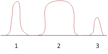
Figure 1. Signals from a detector
The first technique will be amplitude or peak height. As seen below in Figure 2, the point on each graph is the peak of the signal.
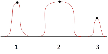
Figure 2. Amplitude or peak height technique
Typically, a higher peak correlates to a higher number of photons in the pulse. However, cases like signal 1 and signal 2 will occur where two peaks are almost the same, but signal 2 would clearly be caused by more light. This means that peak height alone would show that signal 1 and signal 2 are roughly the same magnitude.
The second technique is time over threshold or TOT.
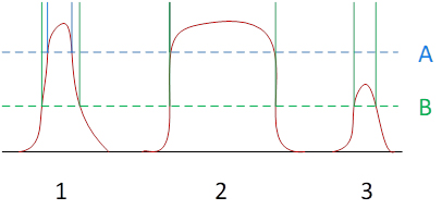
Figure 3. Time over threshold (TOT) technique
With this technique, there is some threshold, which in this case is A and B shown in Figure 3. The measured signal in this case is the time that the signal is above the specified threshold. Selecting a threshold can be difficult, and there is no single right answer as to what the threshold should be. In the case of threshold A, signal 1 and signal 2 have a much larger difference, but signal 3 appears effectively as “0”. With threshold B, signal 1 and signal 2 have a slightly smaller difference, but threshold 3 does appear. In some cases, like with signal 2, changing threshold between A and B will not show a change in signal. In other cases like signal 1 and signal 3, there will be a change in the TOT measurement that is much more noticeable.
Comparing the TOT method to the peak height measurement, both provide useful, real-time data on the amount of light seen in each pulse. There are tradeoffs in each method. For example, the differentiation in signal 1 and signal 3 in the TOT measurement with threshold B is not as significant as the difference in peak height. Another example is that with the peak height method, signal 1 and signal 2 cannot be differentiated easily, but with the TOT method, there is a clear difference.
These are just two potential methods. There are others such as integration for some fixed period of time or integration starting with a threshold. There are also methods that combine different measurement techniques simultaneously and use some algorithm to determine a more accurate amount of light in the pulse.
The information listed here is mainly to understand the signal or charge outputted from the detector. To quantify the amount of light seen by the detector, the quantum efficiency or sensitivity of the detector would need to be incorporated.
If you are interested in learning more about detecting pulses of light, feel free to reach out to our engineers!
Which detector gives me the best signal-to-noise ratio (SNR)?
Which photodetector has the best SNR varies greatly with light level, speed, and support electronics. It’s usually best to determine the light level and which noise source limits you: your signal shot noise, your electronics/amplifier noise, or your detector’s dark noise.
For high light levels where amplifier noise is negligible and you are signal shot noise limited, detectors with the highest quantum efficiency (QE) will have the best SNR.
For lower light levels where the readout or amplifier noise dominates, detectors with high internal gain are required for good SNR. The detector’s internal gain reduces the importance of the amplifier noise, so you are then limited by dark or signal shot noise.
For the lowest light levels, detectors with the lowest dark noise will have the best SNR.
If you’re not sure, we can help! Please contact us to get an SNR calculation for your unique situation.
For more info about choosing a detector, read our Guide to detector selection article.
What is photon counting?
Photon counting is being able to measure and observe a single incident photon. It is typically used with a photon counting specific circuit that discriminates electronics noise out from the observation and removes the excess noise factor, which is noise from the detector’s intrinsic gain mechanism. Using this circuit and because the light levels are so low, we are typically limited by the dark noise of the detector.
What detector options are available for photon counting?
For photon counting, detectors with intrinsic gain are necessary. A commonly used detector is a photomultiplier tube, which uses dynodes to provide intrinsic gain to the detector. Photodiodes do not have intrinsic gain which means 1 incident photon will, at most, allow the flow of 1 electron, which is too small of a signal to overcome the noise. Avalanche photodiodes (APD) have intrinsic gain, but the gain is too small to overcome noise in most cases, unless the APD is run in Geiger mode. Single-photon avalanche diode (SPAD) and Multi-Pixel Photon Counters (MPPC) are based on APDs in Geiger mode, so these two types of detectors have enough intrinsic gain to show single photon pulses.
How can I improve my signal-to-noise ratio (SNR) if I am barely able to differentiate my signal from noise in an MPPC?
If you are limited by the dark noise, it benefits you to try and decrease the dark noise as much as you can to see if you can detect your single photons. One improvement can be using a cooled detector. Examples of a cooled MPPC are the S13362-3050DG and S13362-1350DG. Cooling will help reduce the number of dark counts and dark noise at the cost of needing more power to drive the detector with cooling. If a module is preferred, we do have a variety of cooled modules including the new C14455-GA and C14456-GA series, which have peak sensitivities at 600 nm. If cooling is not preferable for the MPPC and other aspects of the signal/noise cannot be changed, switching the detector family to PMTs may be preferred since PMTs have lower dark counts per unit active area. Please contact Hamamatsu’s Technical Support team if you would like additional information about the tradeoffs and options.
How else can I improve my SNR when I’m photon counting?
Increasing the measurement time can improve your SNR by a factor of the square root of your integration time. Meaning if your current measurements is only 1 second and now you measure the number of signal counts and dark counts for 4 seconds, you will approximately double your SNR!
Here’s the equation for photon counting SNR:
For more information, view a presentation about low light detection.
What is an APD?
APD is short for avalanche photodiode. Similar to other photodetectors, an APD converts light energy (photons) into an electrical current. A silicon APD has spectral sensitivity from the UV to NIR range, and InGaAs APDs extend into the NIR range. An APD is basically a PIN photodiode with the advantage of providing gain. Gain is achieved through a process called impact ionization or the avalanche effect. Applying a large reverse voltage (100 to 500 V) to the APD creates a strong electric field across the PN junction (depletion region) of the APD. The electric field will accelerate electron-hole pairs from within the structure of the APD toward the depletion region. Upon collision with the lattice structure in the depletion region, additional electron-hole pairs are created. The typical gain for an APD is 40 to 100.
What are the advantages and disadvantages of an APD?
Advantages:
- The APD has very high quantum efficiency, so it’s highly sensitive. This feature is advantageous for detecting low light levels.
- The APD is a high-speed device, meaning it has a very fast rise time on the order of 150 ps.
Disadvantages:
- To maximize the gain of the APD, a relatively high reverse voltage is required. The range of the reverse voltage (bias voltage) is from 100 to 500 V.
- The APD is more sensitive to changes in temperature compared to other photodetectors. An increase in temperature will cause a decrease in gain. The parameter used to reference temperature sensitivity is called “temperature coefficient of breakdown voltage,” and its units are given in V/degrees C.
What are the different types of silicon APDs offered by Hamamatsu?
Short wavelength type:
This type of APD has a peak response near 600 nm. This group is broken down into two additional categories: low bias operation type and low terminal capacitance type. The low bias type APDs require bias voltages that are 300 V less than the low terminal capacitance type. The low terminal capacitance types are made for higher speed of operation. If the capacitance of the APD decreases, the rise time also decreases (frequency response increases). The rise time will increase if the effective photosensitive area increases. Typical rise time values for the low capacitance type range from 0.5 to 32 ns.
Near-infrared type:
There are 4 types of near-infrared (NIR) APDs: low bias, low capacitance, 900 nm band/low capacitance, and TE-cooled. The low bias and low capacitance types have similar characteristics as the short wavelength types. The 900 nm band/low capacitance type offers sensitivity near 900 nm along with a high-speed response. The applications for this APD include optical rangefinders and automotive LiDAR. The TE-cooled type APD has a built-in TE-cooler, which keeps the ambient temperature constant. This feature helps to maintain gain stability.
If you have a technical question you’d like to see answered on this page, email us.
Meet the engineers

Eric Mesa is an Applications Engineer out of NJ, who understands the intricacies of signal-to-noise comparisons. He likes baseball and most other sports, and when it comes to detector selection, he always hits a home run!

Neil Patel enjoys the majesty of narwhals and photons. He glides through technical issues just as the unicorn of the sea glides through the water. Fun fact: The narwhal’s tusk is actually a protruding tooth.

Peter Lopez is an Applications Engineer in Hamamatsu’s San Jose, CA, office. He received his Electrical Engineering degree from the University of Michigan, and he has worked in many different industries including semiconductor, infrared detection, microscopy, and medical devices. His past positions have provided a good background for the many different types of markets served by Hamamatsu’s component products. Although originally from Michigan, he’s enjoyed living and working in California for the past 25 years. In his spare time, he enjoys sailing, playing golf, and attending San Jose Sharks hockey games.
- Confirmation
-
It looks like you're in the . If this is not your location, please select the correct region or country below.
You're headed to Hamamatsu Photonics website for US (English). If you want to view an other country's site, the optimized information will be provided by selecting options below.
In order to use this website comfortably, we use cookies. For cookie details please see our cookie policy.
- Cookie Policy
-
This website or its third-party tools use cookies, which are necessary to its functioning and required to achieve the purposes illustrated in this cookie policy. By closing the cookie warning banner, scrolling the page, clicking a link or continuing to browse otherwise, you agree to the use of cookies.
Hamamatsu uses cookies in order to enhance your experience on our website and ensure that our website functions.
You can visit this page at any time to learn more about cookies, get the most up to date information on how we use cookies and manage your cookie settings. We will not use cookies for any purpose other than the ones stated, but please note that we reserve the right to update our cookies.
1. What are cookies?
For modern websites to work according to visitor’s expectations, they need to collect certain basic information about visitors. To do this, a site will create small text files which are placed on visitor’s devices (computer or mobile) - these files are known as cookies when you access a website. Cookies are used in order to make websites function and work efficiently. Cookies are uniquely assigned to each visitor and can only be read by a web server in the domain that issued the cookie to the visitor. Cookies cannot be used to run programs or deliver viruses to a visitor’s device.
Cookies do various jobs which make the visitor’s experience of the internet much smoother and more interactive. For instance, cookies are used to remember the visitor’s preferences on sites they visit often, to remember language preference and to help navigate between pages more efficiently. Much, though not all, of the data collected is anonymous, though some of it is designed to detect browsing patterns and approximate geographical location to improve the visitor experience.
Certain type of cookies may require the data subject’s consent before storing them on the computer.
2. What are the different types of cookies?
This website uses two types of cookies:
- First party cookies. For our website, the first party cookies are controlled and maintained by Hamamatsu. No other parties have access to these cookies.
- Third party cookies. These cookies are implemented by organizations outside Hamamatsu. We do not have access to the data in these cookies, but we use these cookies to improve the overall website experience.
3. How do we use cookies?
This website uses cookies for following purposes:
- Certain cookies are necessary for our website to function. These are strictly necessary cookies and are required to enable website access, support navigation or provide relevant content. These cookies direct you to the correct region or country, and support security and ecommerce. Strictly necessary cookies also enforce your privacy preferences. Without these strictly necessary cookies, much of our website will not function.
- Analytics cookies are used to track website usage. This data enables us to improve our website usability, performance and website administration. In our analytics cookies, we do not store any personal identifying information.
- Functionality cookies. These are used to recognize you when you return to our website. This enables us to personalize our content for you, greet you by name and remember your preferences (for example, your choice of language or region).
- These cookies record your visit to our website, the pages you have visited and the links you have followed. We will use this information to make our website and the advertising displayed on it more relevant to your interests. We may also share this information with third parties for this purpose.
Cookies help us help you. Through the use of cookies, we learn what is important to our visitors and we develop and enhance website content and functionality to support your experience. Much of our website can be accessed if cookies are disabled, however certain website functions may not work. And, we believe your current and future visits will be enhanced if cookies are enabled.
4. Which cookies do we use?
There are two ways to manage cookie preferences.
- You can set your cookie preferences on your device or in your browser.
- You can set your cookie preferences at the website level.
If you don’t want to receive cookies, you can modify your browser so that it notifies you when cookies are sent to it or you can refuse cookies altogether. You can also delete cookies that have already been set.
If you wish to restrict or block web browser cookies which are set on your device then you can do this through your browser settings; the Help function within your browser should tell you how. Alternatively, you may wish to visit www.aboutcookies.org, which contains comprehensive information on how to do this on a wide variety of desktop browsers.
5. What are Internet tags and how do we use them with cookies?
Occasionally, we may use internet tags (also known as action tags, single-pixel GIFs, clear GIFs, invisible GIFs and 1-by-1 GIFs) at this site and may deploy these tags/cookies through a third-party advertising partner or a web analytical service partner which may be located and store the respective information (including your IP-address) in a foreign country. These tags/cookies are placed on both online advertisements that bring users to this site and on different pages of this site. We use this technology to measure the visitors' responses to our sites and the effectiveness of our advertising campaigns (including how many times a page is opened and which information is consulted) as well as to evaluate your use of this website. The third-party partner or the web analytical service partner may be able to collect data about visitors to our and other sites because of these internet tags/cookies, may compose reports regarding the website’s activity for us and may provide further services which are related to the use of the website and the internet. They may provide such information to other parties if there is a legal requirement that they do so, or if they hire the other parties to process information on their behalf.
If you would like more information about web tags and cookies associated with on-line advertising or to opt-out of third-party collection of this information, please visit the Network Advertising Initiative website http://www.networkadvertising.org.
6. Analytics and Advertisement Cookies
We use third-party cookies (such as Google Analytics) to track visitors on our website, to get reports about how visitors use the website and to inform, optimize and serve ads based on someone's past visits to our website.
You may opt-out of Google Analytics cookies by the websites provided by Google:
https://tools.google.com/dlpage/gaoptout?hl=en
As provided in this Privacy Policy (Article 5), you can learn more about opt-out cookies by the website provided by Network Advertising Initiative:
http://www.networkadvertising.org
We inform you that in such case you will not be able to wholly use all functions of our website.
Close