Application notes


Technical notes

Ask an engineer


Publications
United States (EN)
Select your region or country.
Imaging Questions & Answers
- I captured an image of the same sample with two cameras, but the output data from Camera A is overall a higher number than Camera B. Does that mean that Camera B is detecting less light?
- Why turn to InGaAs for NIR detection?
- What is InGaAs “standard wavelength” or “extended wavelength”?
- How can we suppress the dark current of InGaAs image sensors?
- There is no light to my camera, but I still have signal. What does this mean?
- What are the similarities and differences between the many camera interfaces?
- What are some common troubleshooting techniques for connecting a camera?
I captured an image of the same sample with two cameras, but the output data from Camera A is overall a higher number than Camera B. Does that mean that Camera B is detecting less light?
Not necessarily. There are many parameters that go into designing a camera that affect the output number given the same input photons. Each model of camera, even if it uses the same sensor, may have the parameters adjusted differently, resulting in a different output count per detected photon. This ratio of detected photons (photons converted to electrons in each sensor pixel) to the output count is the conversion factor (CF) for the camera, in units of electrons/count and determined by the manufacturer. The conversion factor can also be approximated by the following equation.
Equation 1
The way to compare two cameras is to calculate back to the number of sample photons that the output represents in each case.
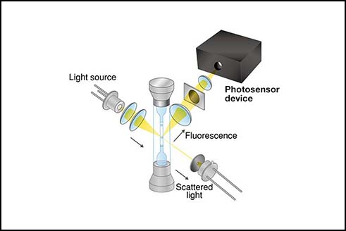
The sensor detects photons (P), which are collected as photoelectrons (e-). The number of detected photons depends on the quantum efficiency (QE, in %), which is wavelength dependent, and on the pixel area, which determines how much of the sample emission is covered with each pixel. The photoelectrons are then converted to a voltage in the readout circuit of the sensor. Gain (G), a multiplication factor, may be added before (EM gain) or after (analog gain) the voltage conversion. This voltage goes into a digitizer which outputs a value represented by a whole number, ranging from the digital offset to the maximum value of the digitizer in units of counts. The equation to calculate the input photons from the output counts is derived from going backwards through the process.
Equation 2
If the pixel sizes in the cameras being evaluated are different, then the number of photons per unit should be calculated and compared using the pixel dimensions, photons/µm2.
As an example of comparing two outputs, let’s use one camera that can output the data in either 16-bit or 12-bit format. The conversion factor would be the only parameter that would change between the two modes.
Given a camera with the following specifications:
- 30,000 e- full well capacity
- 100 count digital offset
- 82% QE at 550 nm
- No gain, G = 1
- 10,000 input photons at 550 nm
The conversion factors for 16 and 12 bits are:
Rewriting equation 2 to solve for counts, we get:
Equation 3
We can see that the output in the 16-bit mode is a higher number than the 12-bit mode, but the input number of photons is the same. The 16-bit mode is not detecting more photons than the 12-bit mode.
When comparing image data between two cameras, or even the same camera with different camera settings, it is important to look at the data and think in photons.
Why turn to InGaAs for NIR detection?
InGaAs is an alloy which belongs to the InGaAsP quaternary system that consists of indium arsenide (InAs), gallium arsenide (GaAs), indium phosphide (InP), and gallium phosphide (GaP). These binary materials and their alloys are all III-V compound semiconductors.
The energy bandgap of InGaAs alloys depends on the ratio of indium and gallium content. At room temperature (300 K), the dependency of the energy bandgap on the indium content x (0~1) can be calculated using the formula: Eg(x) = 1.425eV - 1.501eV*x + 0.436eV*x2. The corresponding cutoff wavelength that can be detected is in the range of 870nm~3.4µm.
| Indium Content x | Energy Gap Eg eV | Corresponding Wavelength nm |
|---|---|---|
| 0 | 1.425 | 870.2 |
| 0.05 | 1.351 | 917.8 |
| 0.1 | 1.279 | 969.3 |
| 0.15 | 1.21 | 1025 |
| 0.2 | 1.142 | 1086 |
| 0.25 | 1.077 | 1151 |
| 0.3 | 1.014 | 1223 |
| 0.35 | 0.953 | 1301 |
| 0.4 | 0.894 | 1386 |
| 0.45 | 0.838 | 1480 |
| 0.5 | 0.783 | 1583 |
| 0.55 | 0.731 | 1696 |
| 0.6 | 0.681 | 1820 |
| 0.65 | 0.634 | 1957 |
| 0.7 | 0.588 | 2109 |
| 0.75 | 0.544 | 2277 |
| 0.8 | 0.503 | 2464 |
| 0.85 | 0.464 | 2671 |
| 0.9 | 0.427 | 2902 |
| 0.95 | 0.393 | 3159 |
| 1 | 0.36 | 3444 |
What is InGaAs “standard wavelength” or “extended wavelength”?
The most used substrate for InGaAs is InP. The InGaAs alloy having x=0.530 has the same lattice constant as InP, which is called "standard InGaAs." This combination brings high quality thin films and results in the cutoff wavelength of 1.7µm.
However, many applications require longer wavelengths. Hamamatsu offers both linear and area InGaAs image sensors with cutoff wavelengths up to 2.6µm, which are called “extended wavelength.” Due to the mismatch of the lattice constant of InGaAs and InP, the quality of the thin films is reduced. However, Hamamatsu put in a lot of effort to guarantee top-quality extended InGaAs.
How can we suppress the dark current of InGaAs image sensors?
The dark current of Hamamatsu InGaAs image sensors is successfully minimized by operating the photodiode array at zero bias condition. Moreover, one-stage TEC (thermoelectric cooler) or multiple-stage TEC can be added into the sensor package to stabilize the sensor temperature and reduce the dark current efficiently.
There is no light to my camera, but I still have signal. What does this mean?
Rewording this question into camera terms, we can say, “The input to the camera sensor is blocked from detecting any photons, but the image data on my computer has non-zero values.”
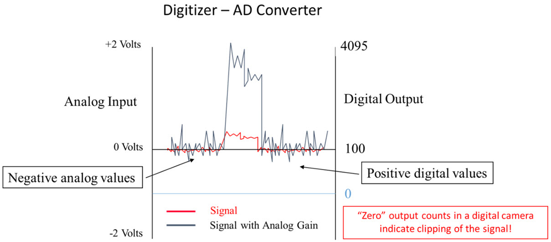
This is an important feature of a scientific digital camera used for quantitative image measurements. To understand why this is the case we need to understand, in very high level terms, the conversion of photons to image data. The sensor detects the photons which are collected as photoelectrons and then passed along as a voltage in the readout circuit of the sensor. This voltage goes into a digitizer, which outputs a value represented by a whole number ranging from 0 to the maximum value of the digitizer. This whole number is referred to as counts, gray values, or gray levels.
The readout of the sensor pixel is an imperfect process and noise is introduced into the signal as it is converted to a voltage reading. This noise is a small fluctuating voltage around the nominal signal. If that signal is 0, then the voltage fluctuates into negative values. Since the digitizer in the camera does not contain values less than zero, these negative voltages would be clipped and data would be lost. To avoid the loss of data, the camera designer will set the zero voltage to be a number higher than zero that will accommodate the noise fluctuation, for example 100 counts on the digitizer. In this case, fluctuations below 0 in voltage would be represented by output counts less than 100 counts.
This non-zero output value for the zero photon input is called the digital offset. The camera manual or camera manufacturer can provide the digital offset number for your camera model. You will need to subtract this digital offset number from each intensity value to determine the true output signal from your camera.
What are the similarities and differences between the many camera interfaces?
Some examples of interfaces that are typically used for cameras are USB 3.0, CameraLink, CoaXPress, Firewire, and GigE. Some factors that are important to consider when comparing these interfaces are speed, throughput, and cable length. The table below compares these interfaces.
| Interface | Approximate speed | Throughput | Cable length |
|---|---|---|---|
| USB 3.0 | 5 Gbits/s | Moderate | 3 m |
| CameraLink | 7 Gbits/s | High | 10 m |
| CoaXPress | 12 Gbits/s | High | 35 m |
| IEEE/Firewire | 3 Gbits/s | Low | 5 m |
| GigE | 1 Gbits/s | Low | 100 m |
What are some common troubleshooting techniques for connecting a camera?
When you are trying to connect a camera to a PC, but are having issues getting the camera to work, you can check a few things. For starters, you want to make sure the camera is powered on and the required cables are properly connected in their respective locations. If you are using a PCIE card, make sure the firmware is updated. You would then need to check that the proper drivers are set up for the interface you are using. This can be done by downloading DCAM-API from our website. If needed, update the camera driver in Device Manager. You can also see if the interface is enabled in the DCAM Configurator. Lastly, verify if the camera is in DCAM Configurator. If the camera is not there, it is most likely a hardware issue. If it is in DCAM Configurator, it is probably a software issue. These are some common techniques that might be useful when having connection issues with cameras.
If you have a technical question you’d like to see answered on this page, email us.
Meet the engineers

Lu Cheng is an applications engineer, specializing in all of our image sensors and driver circuits. Before joining Hamamatsu, she worked as an analog and mixed-signal ASIC designer. With more than 10 years’ experience in ASIC and circuit board design, she can support you to find the optimized product/solution not only from a user’s perspective but also from a designer’s. Traditional Chinese dancing is one of the things that make her learn about the beauty of the world from a different perspective.

Shelley Brankner is an Applications Engineer specializing in scientific cameras and x-ray imaging products. For customers that need high-level synchronization between their camera and peripheral devices, she can provide the expertise on timing and modes of operation in these imaging products. She has a passion for asking the question, “How does that work?” and a desire for sharing the answer with others. When she isn’t knocking down the technical questions that cross her path, she can be found knocking down pins at a bowling alley.

Krishna Mahadas is a Software Engineer at Hamamatsu’s New Jersey branch. As a Software Engineer, he primarily focuses on our camera products, and works with programming languages such as Python and C. He also works with some of our other products such as point detectors. In his free time, he enjoys playing tennis with his friends or brother, and watching the four Grand Slam tennis tournaments.
- Confirmation
-
It looks like you're in the . If this is not your location, please select the correct region or country below.
You're headed to Hamamatsu Photonics website for US (English). If you want to view an other country's site, the optimized information will be provided by selecting options below.
In order to use this website comfortably, we use cookies. For cookie details please see our cookie policy.
- Cookie Policy
-
This website or its third-party tools use cookies, which are necessary to its functioning and required to achieve the purposes illustrated in this cookie policy. By closing the cookie warning banner, scrolling the page, clicking a link or continuing to browse otherwise, you agree to the use of cookies.
Hamamatsu uses cookies in order to enhance your experience on our website and ensure that our website functions.
You can visit this page at any time to learn more about cookies, get the most up to date information on how we use cookies and manage your cookie settings. We will not use cookies for any purpose other than the ones stated, but please note that we reserve the right to update our cookies.
1. What are cookies?
For modern websites to work according to visitor’s expectations, they need to collect certain basic information about visitors. To do this, a site will create small text files which are placed on visitor’s devices (computer or mobile) - these files are known as cookies when you access a website. Cookies are used in order to make websites function and work efficiently. Cookies are uniquely assigned to each visitor and can only be read by a web server in the domain that issued the cookie to the visitor. Cookies cannot be used to run programs or deliver viruses to a visitor’s device.
Cookies do various jobs which make the visitor’s experience of the internet much smoother and more interactive. For instance, cookies are used to remember the visitor’s preferences on sites they visit often, to remember language preference and to help navigate between pages more efficiently. Much, though not all, of the data collected is anonymous, though some of it is designed to detect browsing patterns and approximate geographical location to improve the visitor experience.
Certain type of cookies may require the data subject’s consent before storing them on the computer.
2. What are the different types of cookies?
This website uses two types of cookies:
- First party cookies. For our website, the first party cookies are controlled and maintained by Hamamatsu. No other parties have access to these cookies.
- Third party cookies. These cookies are implemented by organizations outside Hamamatsu. We do not have access to the data in these cookies, but we use these cookies to improve the overall website experience.
3. How do we use cookies?
This website uses cookies for following purposes:
- Certain cookies are necessary for our website to function. These are strictly necessary cookies and are required to enable website access, support navigation or provide relevant content. These cookies direct you to the correct region or country, and support security and ecommerce. Strictly necessary cookies also enforce your privacy preferences. Without these strictly necessary cookies, much of our website will not function.
- Analytics cookies are used to track website usage. This data enables us to improve our website usability, performance and website administration. In our analytics cookies, we do not store any personal identifying information.
- Functionality cookies. These are used to recognize you when you return to our website. This enables us to personalize our content for you, greet you by name and remember your preferences (for example, your choice of language or region).
- These cookies record your visit to our website, the pages you have visited and the links you have followed. We will use this information to make our website and the advertising displayed on it more relevant to your interests. We may also share this information with third parties for this purpose.
Cookies help us help you. Through the use of cookies, we learn what is important to our visitors and we develop and enhance website content and functionality to support your experience. Much of our website can be accessed if cookies are disabled, however certain website functions may not work. And, we believe your current and future visits will be enhanced if cookies are enabled.
4. Which cookies do we use?
There are two ways to manage cookie preferences.
- You can set your cookie preferences on your device or in your browser.
- You can set your cookie preferences at the website level.
If you don’t want to receive cookies, you can modify your browser so that it notifies you when cookies are sent to it or you can refuse cookies altogether. You can also delete cookies that have already been set.
If you wish to restrict or block web browser cookies which are set on your device then you can do this through your browser settings; the Help function within your browser should tell you how. Alternatively, you may wish to visit www.aboutcookies.org, which contains comprehensive information on how to do this on a wide variety of desktop browsers.
5. What are Internet tags and how do we use them with cookies?
Occasionally, we may use internet tags (also known as action tags, single-pixel GIFs, clear GIFs, invisible GIFs and 1-by-1 GIFs) at this site and may deploy these tags/cookies through a third-party advertising partner or a web analytical service partner which may be located and store the respective information (including your IP-address) in a foreign country. These tags/cookies are placed on both online advertisements that bring users to this site and on different pages of this site. We use this technology to measure the visitors' responses to our sites and the effectiveness of our advertising campaigns (including how many times a page is opened and which information is consulted) as well as to evaluate your use of this website. The third-party partner or the web analytical service partner may be able to collect data about visitors to our and other sites because of these internet tags/cookies, may compose reports regarding the website’s activity for us and may provide further services which are related to the use of the website and the internet. They may provide such information to other parties if there is a legal requirement that they do so, or if they hire the other parties to process information on their behalf.
If you would like more information about web tags and cookies associated with on-line advertising or to opt-out of third-party collection of this information, please visit the Network Advertising Initiative website http://www.networkadvertising.org.
6. Analytics and Advertisement Cookies
We use third-party cookies (such as Google Analytics) to track visitors on our website, to get reports about how visitors use the website and to inform, optimize and serve ads based on someone's past visits to our website.
You may opt-out of Google Analytics cookies by the websites provided by Google:
https://tools.google.com/dlpage/gaoptout?hl=en
As provided in this Privacy Policy (Article 5), you can learn more about opt-out cookies by the website provided by Network Advertising Initiative:
http://www.networkadvertising.org
We inform you that in such case you will not be able to wholly use all functions of our website.
Close